X
Our staff will contact you within 12 hours, You can also contact us through the following ways:
Contact US WhatsApp: +86 18263873187
- Email: [email protected]
- Tel: +86 18263873187
- Web: www.lifting-chain.com
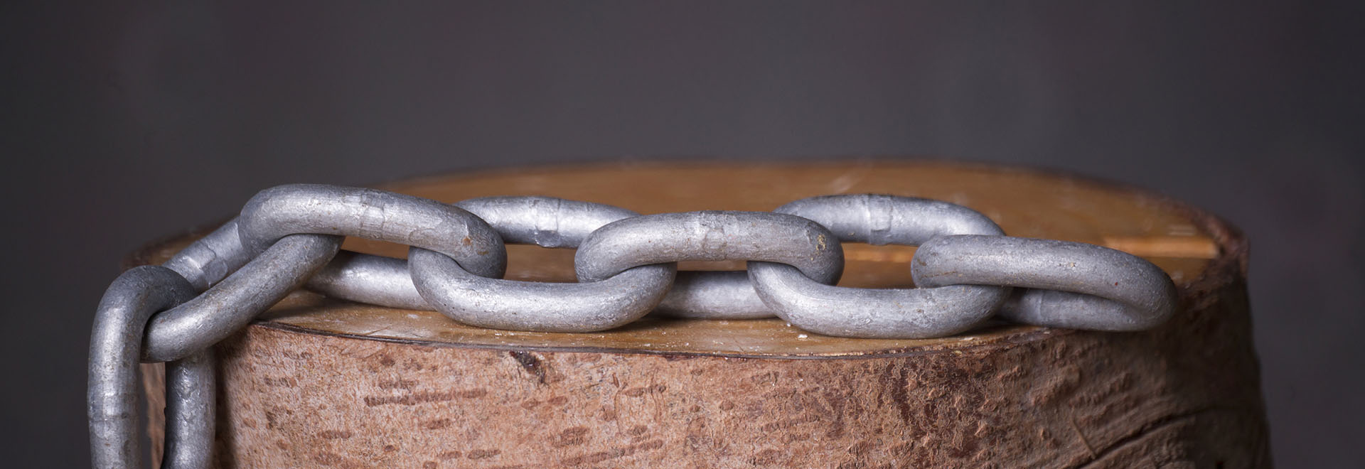
Our 14×50 roundlink mining chain (DIN 22252) completed the required dimensional and tensile steps and passed the breakingload test, with evidence captured in the public video “G80 14x50 Breaking Load Test” (YouTube: EyAD8rLNRZg). We mapped every onscreen step to the DIN 22252 clauses and numerical limits below, so engineers can verify compliance quickly and confidently. We also list the precise dimensional tolerances, hardness band, sampling rules, and acceptance pathway the standard demands, and we reference the sections that govern them.
Scope & intent. DIN 22252 covers roundsteel chains used as traction elements in mining conveyors and faceequipment. The standard specifies material, heat treatment, dimensions, mechanical properties, surface quality, inspection sampling, and acceptance. DIN 22252 chains do not serve as overhead lifting chains; the scope restricts usage to mining conveyors and recovery systems. We respect and state that scope on all product and test media.
Material & heat treat. The standard calls for steel conforming to DIN 17115 (e.g., 23MnNiCrMo52 / 1.6541) with quenchandtemper above Ac₃ to achieve the specified strength and hardness. Our batch followed the weldandheattreat sequence, then proceeded to proof and destructive tests per Section 5–6.
Hardness band. The chain must fall within HV10 350–390 or HBW 345–385 when measured on the nonwelded link arm as defined in Section 6.7. We logged hardness accordingly for the batch records.
Dimensional tolerances. DIN 22252 defines 14×50 as d = 14 ± 0.4 mm, t = 50 ± 0.5 mm, b₁ ≥ 17 mm, b₂ ≤ 48 mm, r (contact radius) 22–24 mm, and 5link gauge length 250 ± 1.0 mm. Technicians measured these values before tensile loading, exactly as Section 6.4 instructs.
Tensile test—forces and strains. The procedure uses a Class1 testing machine (DIN EN ISO 75001), axial fixtures, preload for measurement, then ramp to test force TF and finally to fracture for breaking force BF while recording the force–displacement curve. DIN 22252 sets the 14×50 values in the mechanical table (see §2).
Sampling & acceptance. Section 6 defines batch size and sampling; Section 8 defines acceptance: when all required tests for sampled specimens meet the tables, the batch conforms. Our batch followed that route, and the video provides the visual record of the tensile step.
The standard gives explicit mechanical thresholds for a 14×50 chain; reviewers can compare the onscreen readings with these values.
Parameter | DIN 22252 value for 14×50 | Notes |
Test force, TF | 185 kN | Hold at TF to read strain (Section 6.5). |
Max strain at TF | 1.6 % | Measured over the marked gauge length. |
Minimum breaking force, BF | 246 kN | From table and B.2.3 formula BF ≈ 1.257·d². |
Minimum total elongation at break | 14 % | Derived from the force–displacement curve. |
Minimum bend deflection, f | 14 mm | Bend test per Section 6.6 (no cracks allowed). |
Max working force, WF | 154 kN | For conveyor duty; not an overheadlifting rating. |
Measurement length / force | 200 mm / 8 kN | For length gauging (Table 6). |
How the video aligns. The YouTube clip titled “G80 14x50 Breaking Load Test” shows a 14×50 specimen mounted axially, ramped to a hold level, then pulled to rupture with the live force readout visible. Engineers can pause the frame near peak force and confirm BF ≥ 246 kN, then inspect the curve segment at TF to ensure strain ≤ 1.6 %. This visual record supports the statement that the specimen met the DIN thresholds for BF and strain. (Source video: https://www.youtube.com/watch?v=EyAD8rLNRZg)
Bend test (f). Section 6.6 requires a bend to f = 14 mm without cracks or unacceptable surface flaws. Our quality log records the bend result for this batch. The standard also requires surface checks for cracks after proof load.
Hardness verification. Section 6.7 mandates HV or HB measurements on the nonwelded arm; we performed HV10 readings within 350–390 and archived the values with the batch report.
Optional impact and fatigue. Section 7 allows Charpy impact and fatigue testing by agreement. For larger diameters (≥26 mm), Charpy minima apply explicitly; for 14 mm, fatigue parameters (Fu/Fo) appear in Table 5 as a reference. We plan and execute these extra tests when contracts specify them, then attach results to the acceptance documents.
Marking & certification. Section 9 requires permanent marks (manufacturer, grade, date) at defined intervals and EN 10204 Type 3.1 inspection certificates that list the measured dimensions, TF strain, BF, elongation, hardness, and test remarks. We issue the 3.1 certificate with every DIN 22252 shipment.
Use this short list while you watch:
1. “14×50” on the specimen tag; verify d/t with calipers or preparation shots.
2. Watch the ramp to TF = 185 kN; check strain ≤ 1.6 % at that hold.
3. Observe the peak BF ≥ 246 kN; note the rupture location on the link.
4. Measure postbreak elongation over the marked gauge; confirm A ≥ 14 %.
5.Keep the scope clear: mining conveyor chain, not for overhead lifting.
The 14×50 roundlink chain completed dimensional checks, reached TF = 185 kN within the 1.6 % strain cap, and fractured at or above the 246 kN DIN minimum, so the specimen—and the batch—passed the DIN 22252 acceptance route described in Sections 6–8; engineers can verify each step using the video frame and the numbers above.
Ready to specify or request a 3.1 certificate package? Contact TOPONE and include “DIN 22252 14×50” in your subject line for the fastest response.